{var%20f='http://v.t.sina.com.cn/share/share.php?appkey=1515056452',u=z||d.location,p=['&url=',e(u),'&title=',e(t||d.title),'&source=',e(r),'&sourceUrl=',e(l),'&content=',c||'gb2312','&pic=',e(p||'')].join('');function%20a(){if(!window.open([f,p].join(''),'mb',['toolbar=0,status=0,resizable=1,width=440,height=430,left=',(s.width-440)/2,',top=',(s.height-430)/2].join('')))u.href=[f,p].join('');};if(/Firefox/.test(navigator.userAgent))setTimeout(a,0);else%20a();})(screen,document,encodeURIComponent,'','','https://www.xiaopingtou.cn//data/attach/topic/topicKPo7gB.jpg', '推荐 OREO_GO 的文章《飞思卡尔 K20 CAN FIFO简单笔记》','https://www.xiaopingtou.cn/article-65267.html','页面编码gb2312|utf-8默认gb2312'));)
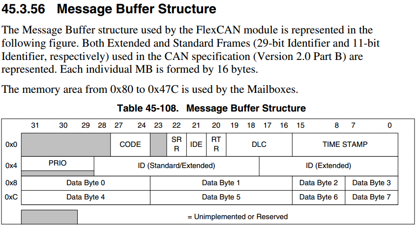
Message Buffer结构:
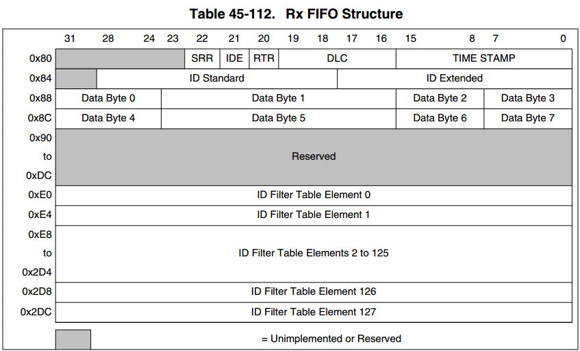
Rx FIFO Structure
When the MCR[RFEN] bit is set, the memory area from 0x80 to 0xDC (which is
normally occupied by MBs 0 to 5) is used by the reception FIFO enginee. 当设置接收为FIFO模式时,MB的0~5会作为接收的FIFO使用。
The region 0x80-0x8C contains the output of the FIFO which must be read by the CPU as
a Message Buffer. This output contains the oldest message received and not read yet. The
region 0x90-0xDC is reserved for internal use of the FIFO engine. X080-0X8C区域MB[0]存放最先接收到的报文,0X90-0XDC存放其它后来接收到的报文。
An additional memory area, that starts at 0xE0 and may extend up to 0x2DC (normally
occupied by MBs 6 up to 37) depending on the CTRL2[RFFN] field setting, contains the
ID Filter Table (configurable from 8 to 128 table elements) that specifies filtering criteria
for accepting frames into the FIFO.
Out of reset, the ID Filter Table flexible memory area defaults to 0xE0 and only extends
to 0xFC, which corresponds to MBs 6 to 7 for RFFN=0, for backward compatibility with
previous versions of FlexCAN.
The following shows the Rx FIFO data structure.
Each ID Filter Table Element occupies an entire 32-bit word and can be compound by
one, two or four Identifier Acceptance Filters (IDAF) depending on the MCR[IDAM]
field setting. The following figures show the IDAF indexation.
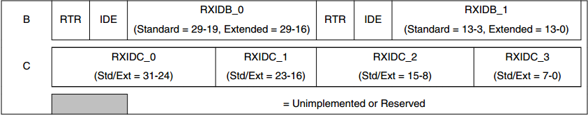
The following figures show the three different formats of the ID table elements. Note that
all elements of the table must have the same format. See Rx FIFO for more information.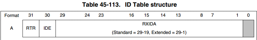
Rx FIFO Structure
When the MCR[RFEN] bit is set, the memory area from 0x80 to 0xDC (which is
normally occupied by MBs 0 to 5) is used by the reception FIFO enginee. 当设置接收为FIFO模式时,MB的0~5会作为接收的FIFO使用。
The region 0x80-0x8C contains the output of the FIFO which must be read by the CPU as
a Message Buffer. This output contains the oldest message received and not read yet. The
region 0x90-0xDC is reserved for internal use of the FIFO engine. X080-0X8C区域MB[0]存放最先接收到的报文,0X90-0XDC存放其它后来接收到的报文。
An additional memory area, that starts at 0xE0 and may extend up to 0x2DC (normally
occupied by MBs 6 up to 37) depending on the CTRL2[RFFN] field setting, contains the
ID Filter Table (configurable from 8 to 128 table elements) that specifies filtering criteria
for accepting frames into the FIFO.
Out of reset, the ID Filter Table flexible memory area defaults to 0xE0 and only extends
to 0xFC, which corresponds to MBs 6 to 7 for RFFN=0, for backward compatibility with
previous versions of FlexCAN.
The following shows the Rx FIFO data structure.
Each ID Filter Table Element occupies an entire 32-bit word and can be compound by
one, two or four Identifier Acceptance Filters (IDAF) depending on the MCR[IDAM]
field setting. The following figures show the IDAF indexation.
The following figures show the three different formats of the ID table elements. Note that
all elements of the table must have the same format. See Rx FIFO for more information.