{var%20f='http://v.t.sina.com.cn/share/share.php?appkey=1515056452',u=z||d.location,p=['&url=',e(u),'&title=',e(t||d.title),'&source=',e(r),'&sourceUrl=',e(l),'&content=',c||'gb2312','&pic=',e(p||'')].join('');function%20a(){if(!window.open([f,p].join(''),'mb',['toolbar=0,status=0,resizable=1,width=440,height=430,left=',(s.width-440)/2,',top=',(s.height-430)/2].join('')))u.href=[f,p].join('');};if(/Firefox/.test(navigator.userAgent))setTimeout(a,0);else%20a();})(screen,document,encodeURIComponent,'','','https://www.xiaopingtou.cn/data/attach/logo/logo.png', '推荐 bailao99 的问题《【征文活动】Working GPIO input interrupt demo for FRDM-K22F with Keniti...》','https://www.xiaopingtou.cn/q-173784.html','页面编码gb2312|utf-8默认gb2312'));)
本帖最后由 bailao99 于 2015-3-17 13:13 编辑
Working GPIO input interrupt demo for FRDM-K22F with Kenitis SDK V1.1.0
The following (after the "- - - - - -") is debugged code for showing SW2, and SW3 pressed or not on the FRDM-K22F module. It is based on Kenitis SDK V1.1.0. It is built with Keil V5.13 and downloaded with JLINK SWD mode.
- - - - - - - - - - - - - - - - - - - - - - - - - - - - - - - - - - - - - - -
#include <string.h>
#include <stdio.h>
#include "fsl_uart_hal.h"
#include "gpio_pins.h"
#include "fsl_clock_manager.h"
#include "fsl_port_hal.h"
#include "board.h"
volatile uint8_t switch_2_isr_entered = 0; // Variable to indicate that the SW2
volatile uint8_t switch_3_isr_entered = 0; // Variable to indicate that the SW3
gpio_input_pin_user_config_t Sw2Pins =
{
.pinName = kGpioSW1,
.config.isPullEnable = false,
.config.pullSelect = kPortPullUp,
.config.isPassiveFilterEnabled = false,
.config.interrupt = kPortIntFallingEdge,
};
gpio_input_pin_user_config_t Sw3Pins =
{
.pinName = kGpioSW2,
.config.isPullEnable = false,
.config.pullSelect = kPortPullUp,
.config.isPassiveFilterEnabled = false,
.config.interrupt = kPortIntFallingEdge,
};
int main(void)
{
// init the hardware board
hardware_init();
// init the debug uart
dbg_uart_init();
/* PB17(Sw3Pin),PC1(Sw2Pin) as GPIO */
PORT_HAL_SetMuxMode(PORTB_BASE,17u,kPortMuxAsGpio);
PORT_HAL_SetMuxMode(PORTC_BASE,0u,kPortMuxAsGpio);
// Initialize the GPIO pins
GPIO_DRV_InputPinInit(&Sw2Pins);
GPIO_DRV_InputPinInit(&Sw3Pins);
printf(" Hello World! ");
for (;;)
{
if(1==switch_2_isr_entered)
{
switch_2_isr_entered = 0;
printf(" SW2 Pressed! ");
}
if(1==switch_3_isr_entered)
{
switch_3_isr_entered = 0;
printf(" SW3 Pressed! ");
}
}
return 0;
}
Prepare the Demo
1. Connect a USB cable between the PC host and the OpenSDA USB port on FRDM-K22F.
2. Open a serial terminal with these settings:
• 115200 baud rate
• 8 data bits
• No parity
• One stop bit
• No flow control
3. Download the program to FRDM-K22F board.
4. Either press the reset button on FRDM-K22F to begin running the demo.
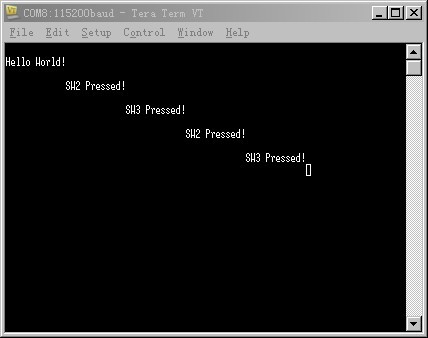
5. Press SW2 switch or SW3 switch to check the result.
Here is output.
 output.jpg (18.79 KB, 下载次数: 0)
下载附件
switch_interrupt_demo ouput
2015-3-17 05:30 上传
output.jpg (18.79 KB, 下载次数: 0)
下载附件
switch_interrupt_demo ouput
2015-3-17 05:30 上传
 switch_interrupt_demo.zip
(22.7 KB, 下载次数: 2)
2015-3-17 05:31 上传
点击文件名下载附件
switch_interrupt_demo.zip
(22.7 KB, 下载次数: 2)
2015-3-17 05:31 上传
点击文件名下载附件
switch_interrupt_demo.zip
Attention: My KSDK V1.1.0 path is D:KSDK_1.1.0. If your KSDK V1.1.0 path is not agree with me, the demo will not work until the configuation in project options->C/C++->Include path,Linker->Scatter File, Linker->Misc controls is correct.
Working GPIO input interrupt demo for FRDM-K22F with Kenitis SDK V1.1.0
The following (after the "- - - - - -") is debugged code for showing SW2, and SW3 pressed or not on the FRDM-K22F module. It is based on Kenitis SDK V1.1.0. It is built with Keil V5.13 and downloaded with JLINK SWD mode.
- - - - - - - - - - - - - - - - - - - - - - - - - - - - - - - - - - - - - - -
#include <string.h>
#include <stdio.h>
#include "fsl_uart_hal.h"
#include "gpio_pins.h"
#include "fsl_clock_manager.h"
#include "fsl_port_hal.h"
#include "board.h"
volatile uint8_t switch_2_isr_entered = 0; // Variable to indicate that the SW2
volatile uint8_t switch_3_isr_entered = 0; // Variable to indicate that the SW3
gpio_input_pin_user_config_t Sw2Pins =
{
.pinName = kGpioSW1,
.config.isPullEnable = false,
.config.pullSelect = kPortPullUp,
.config.isPassiveFilterEnabled = false,
.config.interrupt = kPortIntFallingEdge,
};
gpio_input_pin_user_config_t Sw3Pins =
{
.pinName = kGpioSW2,
.config.isPullEnable = false,
.config.pullSelect = kPortPullUp,
.config.isPassiveFilterEnabled = false,
.config.interrupt = kPortIntFallingEdge,
};
int main(void)
{
// init the hardware board
hardware_init();
// init the debug uart
dbg_uart_init();
/* PB17(Sw3Pin),PC1(Sw2Pin) as GPIO */
PORT_HAL_SetMuxMode(PORTB_BASE,17u,kPortMuxAsGpio);
PORT_HAL_SetMuxMode(PORTC_BASE,0u,kPortMuxAsGpio);
// Initialize the GPIO pins
GPIO_DRV_InputPinInit(&Sw2Pins);
GPIO_DRV_InputPinInit(&Sw3Pins);
printf(" Hello World! ");
for (;;)
{
if(1==switch_2_isr_entered)
{
switch_2_isr_entered = 0;
printf(" SW2 Pressed! ");
}
if(1==switch_3_isr_entered)
{
switch_3_isr_entered = 0;
printf(" SW3 Pressed! ");
}
}
return 0;
}
Prepare the Demo
1. Connect a USB cable between the PC host and the OpenSDA USB port on FRDM-K22F.
2. Open a serial terminal with these settings:
• 115200 baud rate
• 8 data bits
• No parity
• One stop bit
• No flow control
3. Download the program to FRDM-K22F board.
4. Either press the reset button on FRDM-K22F to begin running the demo.
5. Press SW2 switch or SW3 switch to check the result.
Here is output.
output.jpg (18.79 KB, 下载次数: 0)
下载附件
switch_interrupt_demo ouput
2015-3-17 05:30 上传
switch_interrupt_demo.zip
(22.7 KB, 下载次数: 2)
2015-3-17 05:31 上传
点击文件名下载附件
switch_interrupt_demo.zip
Attention: My KSDK V1.1.0 path is D:KSDK_1.1.0. If your KSDK V1.1.0 path is not agree with me, the demo will not work until the configuation in project options->C/C++->Include path,Linker->Scatter File, Linker->Misc controls is correct.
一周热门 更多>